
PTFE Backup Rings: Anti-Extrusion Retainers for Aerospace Hydraulic and Pneumatic Systems
Engineering reference for PTFE backup rings (packing retainers): extrusion mechanics, single versus double configurations, cut geometry, and the MS28774, MS28782, MS27595, AS5781 and AS8791 specifications.
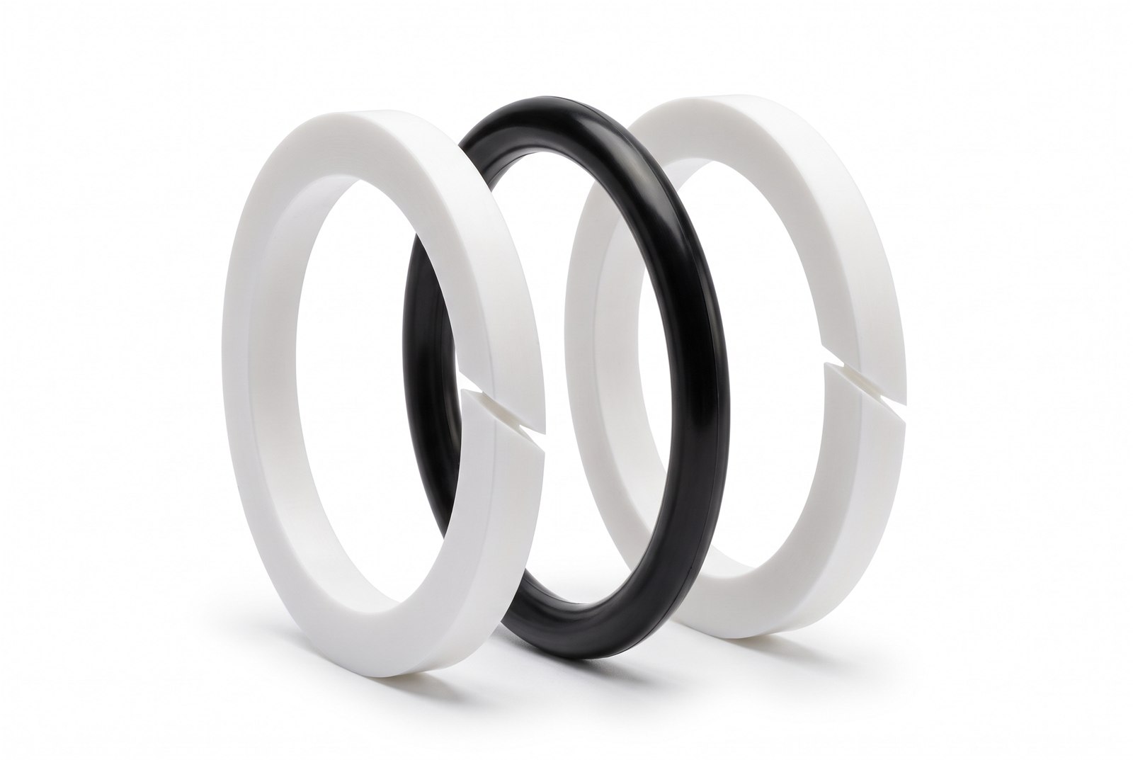
A backup ring is a rectangular cross section retainer installed in the seal gland adjacent to the O-Ring, and its single function is to prevent extrusion of the elastomer into the diametral clearance gap. It carries no sealing duty of its own. Under differential pressure the O-Ring is displaced against the downstream groove wall, and if the combination of pressure, temperature, fluid compatibility and clearance exceeds what the elastomer can bridge, material flows into the gap and the seal is lost. A backup ring machined from PTFE or a comparable polymer deforms under that same pressure to occupy the gap, holding effective extrusion clearance at essentially zero and providing positive support to the O-Ring. Backup rings are effective in both static and dynamic service.
The extrusion mechanism
Extrusion is a mechanical failure, not a chemical one. System pressure acts on the upstream face of the O-Ring and packs the elastomer against the low pressure side of the groove. The elastomer then behaves as a highly viscous fluid confined by the groove walls and the mating surface. Where the two hardware members do not touch, the clearance gap presents an unsupported span, and the elastomer creeps into it.
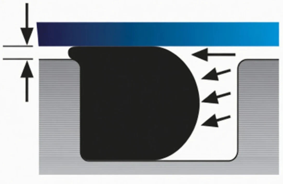
Four variables govern whether extrusion occurs, and they compound:
- Differential pressure. The driving force. A 70 durometer nitrile in a nominal gland begins to extrude in the neighborhood of 1,500 psi. Aircraft hydraulic systems run 3,000 psi as the long-standing standard, and 5,000 psi on newer platforms.
- Diametral clearance. The unsupported span. Clearance is not a single design number. It is the worst case stack of bore and piston tolerances, plus concentricity error, plus pressure-induced bore dilation, plus differential thermal growth between dissimilar materials.
- Temperature. Elastomer modulus falls as temperature rises, so the same ring bridges less gap when hot. Thermal expansion of the housing widens the gap at the same time.
- Fluid compatibility. Media that swells or plasticizes the elastomer reduce its modulus and tear strength. The ring may be chemically serviceable and still lose the mechanical properties it needs to resist extrusion.
That last point deserves emphasis, because it is the one that surprises people. A hostile environment can degrade extrusion resistance through temporary or permanent change in the elastomer’s physical properties, well before there is any visible chemical attack. The ring looks acceptable and fails mechanically anyway.
The signature on a returned part is unmistakable: a ragged, nibbled or feathered edge on the downstream side of the ring, sometimes with material torn away entirely. See Failure Analysis for the comparison against compression set and spiral failure.
How the backup ring restores the gland
The retainer is installed downstream of the O-Ring, between the seal and the clearance gap. It is stiffer than the elastomer and it is dimensioned to the groove, so under pressure it deforms to conform to the gap geometry rather than flowing through it. The O-Ring then bears against a solid, continuous surface instead of an open span.
The consequence for design is that the extrusion limit stops being the constraint. The gland can then be pushed to higher pressure, run at wider clearance, tolerate more thermal growth or accept a softer compound, depending on which of those the application actually needs.
Why PTFE
PTFE is the default retainer material in aerospace fluid power for reasons that are specific to this duty:
- Controlled deformation under load. PTFE cold flows. In most sealing contexts that is a liability, and on the PTFE material page we treat it as one. In a backup ring it is the working principle. The retainer conforms to the clearance gap under pressure and closes it.
- Near-universal media compatibility. PTFE is inert to the petroleum and synthetic hydrocarbon hydraulic fluids covered by MIL-PRF-5606, MIL-PRF-83282 and MIL-PRF-87257, to phosphate ester fluids, to fuels, to oxygen service and to essentially every gas of interest. The retainer is not the limiting element in the fluid compatibility analysis.
- Temperature span. A published range of -100°F to +500°F (-73°C to +260°C) brackets the service window of every common O-Ring elastomer, including cryogenic work where rubber has long since vitrified.
- Low friction. Coefficient of friction is low enough that a retainer in a dynamic gland does not meaningfully add breakout force or drive the O-Ring toward spiral failure.
- Performance in hostile environments. Where the media has softened the elastomer and cost it extrusion resistance, the PTFE retainer is unaffected and carries the gap on its own.
Configurations
Single versus double
Single retainer for unidirectional pressure. Install it on the low pressure side, downstream of the O-Ring. A retainer on the upstream side does nothing and wastes groove width.
Double retainers for bidirectional pressure, which covers any double-acting actuator, any piston that sees pressure on both strokes and any static joint subject to reversal or vacuum. One retainer on each side of the O-Ring. This is the arrangement in the photograph at the top of this article: identical retainers flanking an O-Ring of the same nominal size.
Either configuration requires a wider groove than the O-Ring alone. Design that width in from the beginning against the applicable gland standard. Retrofitting a retainer into a groove sized for a bare O-Ring over-fills the gland, and an over-filled gland is its own failure mode. See Groove Design and the Master O-Ring Size Chart, where the AS568 Backup standard shows backup-specific width and height columns alongside the companion O-Ring dash size.
Cut geometry
| Geometry | Description | Selection notes |
|---|---|---|
| Continuous (solid, uncut) | A one-piece ring with no split. | Maximum extrusion resistance and no discontinuity for the elastomer to find. Requires the gland to be openable or the ring to be stretched over the piston during assembly, which limits how far it can be installed without damage. |
| Single turn (scarf cut) | One diagonal cut through the section. | The standard aerospace retainer. The scarf opens for installation over a piston or into a bore, then closes under pressure. The angled cut keeps the joint supported rather than presenting a square butt. |
| Spiral cut | A continuous helix of two or more turns. | Installs onto closed geometry without stretch and gives a long overlapping joint. Heavier section and more groove width. |
| Contoured | Concave face profiled to the O-Ring section. | Cradles the elastomer and distributes contact rather than loading one edge. The concave face installs toward the O-Ring. |
Non-standard sizes and special geometries are produced routinely, so an unusual gland is not a reason to redesign around a stock ring.
Aerospace and military specifications
Retainers are procured to specification, not to description. These are the callouts that appear on aerospace drawings and bills of material.
Single turn, scarf cut
| Specification | Title |
|---|---|
| MS28774 | Retainer, Packing Backup, Single Turn, Polytetrafluoroethylene |
| AS5781 | Retainers (Backup Rings), Hydraulic and Pneumatic, Polytetrafluoroethylene Resin, Single Turn, Scarf-Cut, For Use in AS4716 Glands |
| AS5860 | Retainers (Backup Rings), Hydraulic and Pneumatic, Polytetrafluoroethylene Resin, Single Turn, Scarf-Cut, For Use in AS5857 Static Glands |
Continuous, solid, uncut
| Specification | Title |
|---|---|
| MS27595 | Retainer, Packing Backup, Continuous Ring, Polytetrafluoroethylene |
| AS5782 | Retainers (Backup Rings), Hydraulic and Pneumatic, Polytetrafluoroethylene Resin, Solid, Un-Cut, for Use in AS4716 Glands |
| AS5861 | Retainers (Backup Rings), Hydraulic and Pneumatic, Polytetrafluoroethylene Resin, Solid, Un-Cut, for Use in Static Glands to AS5857 |
Boss and straight thread tube fitting
| Specification | Title |
|---|---|
| MS28773 | Retainer, Packing, Back-Up, Tetrafluoroethylene, Straight Thread Tube Fitting Boss |
| MS9058 | Ring, Back-Up, Boss Connection |
General PTFE retainer standards
| Specification | Title |
|---|---|
| MS28782 | Retainer, Packing, Back-Up, Teflon |
| AS8791 (M8791/1) | Hydraulic and Pneumatic Retainers (Backup Rings), Polytetrafluoroethylene (PTFE) |
Procurement note: the same physical retainer frequently satisfies more than one of these callouts. Give us the specification number and the companion O-Ring dash size and we will confirm the cross reference rather than have you guess at it.
Gland standards
Retainers are dimensioned to the gland, so the gland standard drives the part. We supply continuous, single turn scarf cut, spiral cut and special geometries for:
- MIL-G-5514, the long-standing military gland design standard for O-Ring packings
- AS4716, dynamic and static gland design for hydraulic and pneumatic service
- AS5857, static gland design
- AS5202, straight thread O-Ring port and fitting ends
- AS5179, gland design for related fluid power applications
For the wider set of military O-Ring callouts, see the mil-spec reference.
Design and installation notes
- Size the groove first. Retainer width is additive to the O-Ring section. Take the groove width from the gland standard’s backup ring column, not from the bare O-Ring column.
- Orient single retainers downstream. If pressure can reverse even briefly, treat the application as bidirectional and use two.
- Stagger the scarf cuts when two scarf-cut retainers are installed, so the two joints do not land on the same angular position.
- Contoured retainers face the O-Ring with the concave side, so the elastomer is cradled rather than loaded across an edge.
- Chamfer and deburr the lead-in. PTFE is notch sensitive. A sharp thread crest or port edge will score a retainer during assembly, and the score becomes the extrusion path.
- Do not reuse retainers. A PTFE ring that has held pressure has taken a permanent set to the gap it was closing. It will not close a different one.
- Verify clearance at temperature. Run the gap calculation at maximum operating temperature with worst case tolerances and pressure-induced dilation, not at room temperature nominal.
Features and benefits
- Positive extrusion protection for the O-Ring
- Longer service life from the seal already specified
- Higher working pressure without changing compound or hardware
- Near-unlimited media and gas compatibility
- Straightforward installation, particularly in the scarf-cut geometry
- A wide range of geometries to suit the gland rather than the reverse
- Established industry part standards with traceable procurement
Frequently asked questions
What does a backup ring actually do?
It prevents extrusion. A backup ring is a rectangular cross section retainer installed next to the O-Ring on the low pressure side, where it occupies the diametral clearance gap so the elastomer has nowhere to flow under pressure. It performs no sealing function itself.
When do I need a backup ring?
When differential pressure, clearance, temperature or media exceed what the O-Ring alone can bridge. As a starting point, a 70 durometer elastomer in a nominal gland begins to extrude near 1,500 psi, so aircraft hydraulic systems at 3,000 psi and 5,000 psi are firmly in retainer territory. Wide or uncontrolled clearance, elevated temperature and media that soften the elastomer all lower that threshold.
One backup ring or two?
One if pressure acts from a single direction, installed downstream of the O-Ring. Two if pressure can reverse, which covers double-acting actuators and any joint that may see vacuum or back pressure. Both cases need the groove width designed for the retainers from the start.
What is the difference between scarf cut and continuous backup rings?
A scarf-cut (single turn) retainer has one diagonal split, so it opens for installation over a piston or into a bore and closes under pressure. A continuous retainer is solid with no split, which gives maximum extrusion resistance but requires openable hardware or stretch during assembly. Scarf cut is the common aerospace choice, and both are covered by their own specifications.
Which specification should I order to?
Match the gland standard. AS5781 and AS5782 serve AS4716 glands, AS5860 and AS5861 serve AS5857 static glands, MS28774 and MS27595 are the legacy single turn and continuous military callouts, and MS28773 and MS9058 cover straight thread boss connections. If the drawing gives you a number, order to the number.
Are PTFE backup rings compatible with my hydraulic fluid?
Effectively always. PTFE is inert to MIL-PRF-5606, MIL-PRF-83282 and MIL-PRF-87257 hydraulic fluids, to phosphate esters, to fuels and to the gases used in pneumatic and oxygen service. The compatibility question belongs to the O-Ring compound, not to the retainer. See the chemical compatibility chart.
Can I add a backup ring to an existing groove?
Only if the groove was dimensioned for it. Adding a retainer to a groove sized for a bare O-Ring over-fills the gland, and an over-filled gland fails on its own. Check the groove width against the backup ring column of the applicable gland standard before making the change.
Why buy PTFE backup rings from The O-Ring Store LLC
Aerospace sealing does not reward guesswork. When you order retainers from us:
- ISO 9001:2015 certified quality with Certificate of Conformance, cure date and lot traceability on request.
- Specification cross referencing across the MS and AS callouts, so a legacy drawing number gets matched to a current, procurable part.
- Continuous, single turn scarf cut, spiral cut and special geometries, including non-standard sizes when the gland calls for one.
- Olypsys® scan-based verification checks the right part into every order.
- Real people in Clarkston, Washington who work seals every day and answer the phone.
Shop PTFE back-up rings at The O-Ring Store, ISO 9001:2015 certified, CAGE Code 72PR0. Send us the specification number, the companion O-Ring dash size or the full drawing and we will match the retainer to your gland.
For detailed selection and application methodology, reference SAE AIR1802, “Selection and Application of Polytetrafluoroethylene (PTFE and TFE) Backup Rings for Hydraulic and Pneumatic Fluid Power Applications.” Specification titles are given as published for identification. Extrusion and gland guidance draws in part on the Freudenberg FST 2025 Technical Manual, ch. 6 (Static Seals), §14 Back-Up Rings. Confirm suitability for your specific service before use. Teflon® is a mark of its respective owner and is referenced here for identification of the material we supply. See also the design reference on Back-Up Rings and the material page for PTFE.