
O-Ring Groove & Gland Dimension Charts
The complete O-Ring groove reference: interactive gland dimension charts for radial, face, dovetail, hydraulic, pneumatic, and floating styles, plus squeeze, fill, extrusion, finish, and install chamfer guides.
The practical place to size an O-Ring gland (groove): interactive dimensions for every common style, crisp diagrams, and the design rules that keep seals from leaking, extruding, or failing on install.
Pair this with the Master O-Ring Size Chart for dash numbers and the Groove Calculator for quick math.
Interactive reference
Gland style explorer
Pick a groove style, search by cross-section, and read depth, width, radii, and approximate squeeze in inch or mm.
- 5–30%static radial squeeze
- 10–35%static face squeeze
- ≤90%max gland fill
Static radial (piston / rod)
- CS
- cord diameter
- t / h
- groove depth
- b
- groove width
- z
- lead-in
- r1 / r2
- corner radii
| Loading… |
Loading interactive chart…
Surface finish for this style
Ra targets assume about 50% or greater material ratio (tp).
| Surface | Duty | Ra (µin) | Rmax (µin) |
|---|
Preferred AS568 cord sizes are highlighted (0.070, 0.103, 0.139, 0.210, 0.275 in). Click a column header to sort. Related: Groove Design, Master O-Ring Size Chart, Groove Calculator. Confirm critical fits on your drawing.
Jump links
| Topic | What you get |
|---|---|
| Seal types | Male, female, face, triangular, dovetail |
| Squeeze & fill | Compression ratio targets and fill limits |
| Interference | Stretch/crush and CS shrink |
| Extrusion | Gap vs pressure × hardness |
| Details | Wall angle, radii, finish, chamfer |
| Checklist | End-to-end design steps |
Seal types
Most static O-Ring seals use one of three rectangular glands. Special pockets (triangular, dovetail) show up when retention or hardware geometry forces them. Diagrams match the Groove Calculator cross-section style: installed ring in the groove, free-state outline dashed.
Male gland (piston)
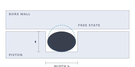
Groove in the piston OD. Assembly enters the bore. Seals radially.
Female gland (rod)
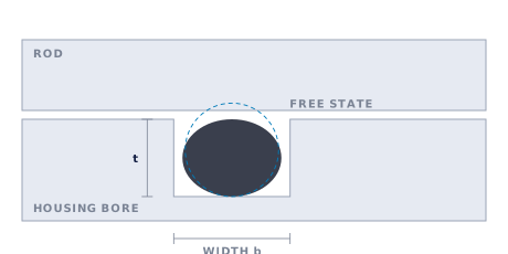
Groove in the bore ID. Smooth rod passes through the ring. Seals radially.
Face seal
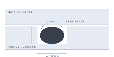
Groove in a flat face. Mating face closes on the ring. Seals axially.
Dovetail
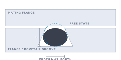
Undercut face groove (~24°). Holds the ring when the joint opens.
Triangular
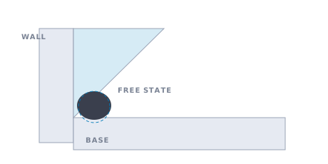
V-pocket between parts. Less common. Prototype and test carefully.
Height and width (how chart numbers map)
| Seal type | Gland height (depth) | Gland width |
|---|---|---|
| Male | (Bore Ø − Gland Ø) / 2 | Groove width in the piston |
| Female | (Gland Ø − Rod Ø) / 2 | Groove width in the bore |
| Face | Groove depth h | (Gland OD − Gland ID) / 2 |
- Height is less than CS so the ring is squeezed (sealing surfaces).
- Width is greater than CS so the ring can spread (containing surfaces).
The interactive table’s depth and width columns are those two numbers for a chosen cross-section and style.
Squeeze and gland fill
Compression ratio
Squeeze = CS − gland height
Compression ratio = (CS − height) / CS × 100
Always check stack-up: largest ring in smallest groove, and smallest ring in largest groove. Nominal-only math hides under-squeeze.
| Arrangement | Min | Target | Max |
|---|---|---|---|
| Static radial (male/female) | 5% | ~20% | 30% |
| Static face | 10% | ~25% | 35% |
| Dynamic (hydraulic / pneumatic) | ~5% | lower half of static | ~20% |
Keep absolute squeeze above about 0.1 mm (0.005 in) after tolerances.
Gland fill
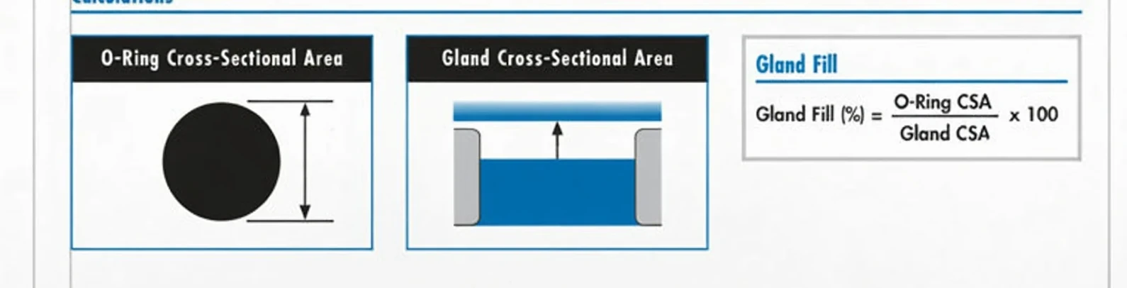
Gland fill (%) = (π × (CS/2)²) / (height × width) × 100 (rectangular groove)
| Min | Target band | Max |
|---|---|---|
| 50% | 65–85% | 90% |
Overfill drives extrusion and install damage. Underfill can let a dynamic ring roll.
ID/OD interference
| Seal type | Fit goal | Typical limit |
|---|---|---|
| Male | Light stretch on ID | 0–5% ID stretch |
| Female | Light OD interference | 0–2% on OD |
| Face, external pressure | ID seats on gland ID | 0–5% on ID |
| Face, internal pressure | OD seats on gland OD | 0–3% on OD |
CS shrinks when the ring stretches
Use the reduced cord size for squeeze/fill math when stretch is non-trivial.
| AS568 series | Free CS | ~1% | ~3% | ~5% |
|---|---|---|---|---|
| 0xx | 0.070 in / 1.78 mm | 0.069 / 1.76 | 0.068 / 1.74 | 0.068 / 1.72 |
| 1xx | 0.103 / 2.62 | 0.102 / 2.59 | 0.100 / 2.56 | 0.100 / 2.53 |
| 2xx | 0.139 / 3.53 | 0.138 / 3.49 | 0.136 / 3.44 | 0.134 / 3.41 |
| 3xx | 0.210 / 5.33 | 0.208 / 5.28 | 0.205 / 5.20 | 0.203 / 5.15 |
| 4xx | 0.275 / 6.99 | 0.272 / 6.92 | 0.268 / 6.82 | 0.266 / 6.75 |
Extrusion and back-up rings
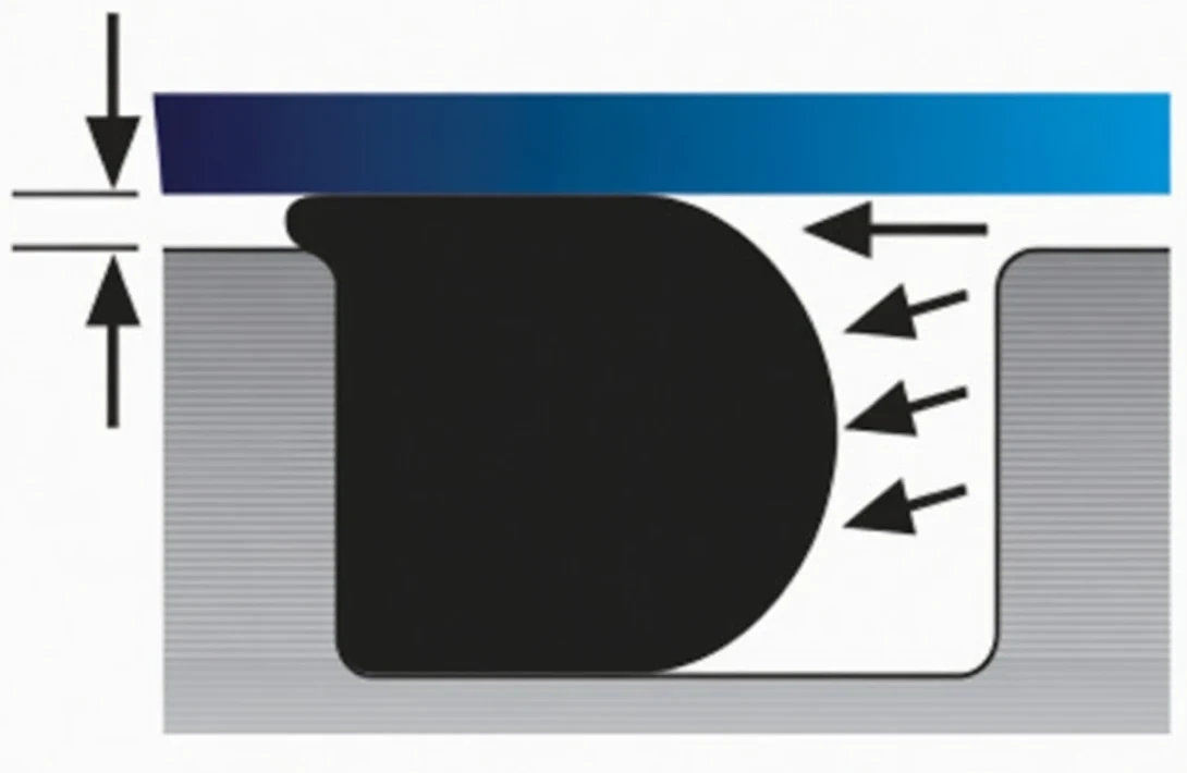
Max diametric clearance (inch, mm in parentheses)
| Pressure (psi) | 60 Shore A | 70 | 80 | 90 |
|---|---|---|---|---|
| 500 | 0.010 (0.25) | 0.015 (0.38) | 0.020 (0.51) | 0.025 (0.64) |
| 750 | 0.005 (0.13) | 0.011 (0.28) | 0.016 (0.41) | 0.023 (0.58) |
| 1,000 | 0.002 (0.05) | 0.008 (0.20) | 0.012 (0.30) | 0.018 (0.46) |
| 1,250 | 0.001 (0.02) | 0.004 (0.10) | 0.009 (0.23) | 0.015 (0.38) |
| 1,500 | redesign | 0.002 (0.05) | 0.007 (0.18) | 0.012 (0.30) |
If you cannot hold the gap, add a back-up ring on the low-pressure side (or both sides for reversing pressure). Widen the groove by the back-up thickness.
Groove details
Wall angle
Keep side walls between 0° and 5° (near vertical).
Transition radii (guideline)
| CS (mm) | CS (in) | r1 (mm / in) | r2 (mm / in) |
|---|---|---|---|
| 1–2 | 0.04–0.08 | 0.10 / 0.004 | 0.30 / 0.012 |
| 2–3 | 0.08–0.12 | 0.20 / 0.008 | 0.30 / 0.012 |
| 3–4 | 0.12–0.16 | 0.20 / 0.008 | 0.50 / 0.020 |
| 4–5 | 0.16–0.20 | 0.20 / 0.008 | 0.60 / 0.024 |
| 5–6 | 0.20–0.24 | 0.20 / 0.008 | 0.60 / 0.024 |
| 6–8 | 0.24–0.31 | 0.20 / 0.008 | 0.80 / 0.031 |
| 8–10 | 0.31–0.39 | 0.20 / 0.008 | 1.00 / 0.039 |
| 10–12 | 0.39–0.47 | 0.20 / 0.008 | 1.00 / 0.039 |
| 12–15 | 0.47–0.59 | 0.20 / 0.008 | 1.20 / 0.047 |
Surface finish (max Ra)
| Surface | Constant pressure | Pulsating |
|---|---|---|
| Sealing face A | 1.6 µm / 64 µin | 0.8 µm / 32 µin |
| Sealing face B / groove bottom | 3.2 µm / 128 µin | 1.6 µm / 64 µin |
| Containing walls | 6.3 µm / 256 µin | 3.2 µm / 128 µin |
Installation chamfer (radial seals)
About 15° on the bore or rod, long enough that the ring only sees the chamfer.
| CS (in / mm) | Min length (in / mm) |
|---|---|
| 0.070 / 1.78 | 0.083 / 2.10 |
| 0.103 / 2.62 | 0.122 / 3.10 |
| 0.139 / 3.53 | 0.157 / 4.00 |
| 0.210 / 5.33 | 0.236 / 6.00 |
| 0.275 / 6.99 | 0.283 / 7.20 |
Install checklist: no over-stretch, deburr, clean, lube, soft tools, no twist or roll into the groove.
Design checklist
- Choose style (male, female, face, dovetail, hydraulic, pneumatic, floating).
- Pick the largest practical CS; prefer AS568 / ISO preferred sizes when you can.
- Set depth for squeeze in range; verify min and max stack-up.
- Set width for gland fill about 65–85% (never over ~90%).
- Apply ID/OD interference; use reduced CS if stretch is meaningful.
- Control extrusion gap; add back-up rings if needed.
- Spec wall angle, radii, finish, and chamfer.
- Confirm compound on Materials and the Chemical Compatibility Chart.
- Test in real hardware. Guidelines are a start, not a substitute for validation.
Need a ring for a finished groove? Measure the groove, then filter CS and ID on the Master O-Ring Size Chart, or contact The O-Ring Store.
Industrial practice for static O-Ring glands (ISO 3601 preferred cord sizes and AS568 series). Always verify against your print, pressure, and compound.