
O-Ring Groove & Gland Design Guide
How to design an O-Ring gland: squeeze, gland fill, groove width, clearance gap, and surface finish, for static and dynamic seals.
The groove, or gland, is where the seal is won or lost. Compound and size get most of the attention, but a ring in a badly cut groove leaks no matter how good the rubber is. Four numbers do most of the work: squeeze, gland fill, clearance gap, and surface finish.
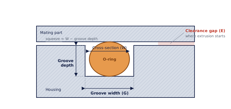
Squeeze
Squeeze is how much the ring is flattened when the joint closes, given as a percentage of the cross-section. It is what makes first contact and holds a seal before pressure ever arrives (see Sealing Principles).
| Seal type | Typical squeeze |
|---|---|
| Static, face (axial) | About 18 to 30 percent |
| Static, radial | About 15 to 25 percent |
| Dynamic, reciprocating | About 8 to 16 percent |
| Rotary | About 3 to 10 percent (low, to limit heat) |
Too little squeeze leaks. Too much builds heat and drives compression set, and it makes a dynamic ring drag and wear. Moving seals run less squeeze on purpose so they don’t cook themselves with friction.
Gland fill
An O-Ring has to have room to move. Rubber is nearly incompressible, so as the ring is squeezed it spreads sideways, and it also grows when it gets hot or swells slightly in the media. The groove has to leave space for all of that.
Design the groove so the ring fills about 60 to 85 percent of the groove volume, never more than roughly 90 percent. Overfill a groove and a hot, slightly swollen ring has nowhere to go, so it forces itself into the clearance gap and extrudes. Underfill it and a dynamic ring can roll. When in doubt, leave room.
Groove width and depth
- Depth sets the squeeze. Groove depth is cut shallower than the cross-section by the squeeze amount above.
- Width gives the flattened ring somewhere to spread and holds gland fill in range. Standard practice runs the groove width at roughly 1.2 to 1.5 times the cross-section. Widen it a little if you are adding a back-up ring.
Want the actual numbers? Two ways to get them:
- The Groove Charts page has depth, width, radii, and finish for every common style (static radial and face, dovetail, hydraulic, pneumatic, floating). Use it to browse and compare.
- The O-Ring Groove Calculator works one job at a time. Give it your dash number and your bore or rod diameter and it returns the groove to machine, the squeeze and gland fill you end up with, and how far the ring stretches.
The Sizing page has the size and dash-number side. Ask us for the machined gland dimensions for your specific ring and duty.
Clearance gap
The clearance gap is the space between the two hardware parts at the low-pressure side of the ring, where extrusion happens. The smaller the gap, the more pressure the seal takes before rubber starts squeezing into it.
Gap tolerance, ring hardness, and pressure all trade against each other. As a rough guide, standard 70-durometer rings start to extrude past roughly 1,500 psi with a typical gap. You buy back headroom three ways: tighten the gap, go to a harder 90-durometer compound, or add a back-up ring. See Shore A Hardness for the extrusion-gap chart, and Back-Up Rings for anti-extrusion rings.
Surface finish
The ring seals against a surface, so the surface matters as much as the groove.
| Surface | Typical finish (Ra) |
|---|---|
| Static sealing faces | 32 to 63 µin (0.8 to 1.6 µm) |
| Dynamic sealing surface | 8 to 16 µin (0.2 to 0.4 µm) |
| Groove side and bottom walls | up to 32 to 63 µin (0.8 to 1.6 µm) |
Too rough and a dynamic ring wears fast and leaks along the scratches. Too smooth, like a mirror polish on a moving rod, and the ring can’t hold a lubricating film and runs dry. There is a sweet spot, and it is finer for dynamic than static.
Don’t forget the lead-in
Any edge the ring slides over on assembly needs a chamfer (a lead-in angle) and no sharp burrs, or the ring gets cut going in. That is an installation detail, but you design it into the part. See Installation for chamfer angles and handling.
Get squeeze, gland fill, clearance gap, and surface finish right and most seal failures never happen. Get one wrong and the Failure Analysis page tells you which leak you just designed in.
Gland design guidance based in part on the Freudenberg FST 2025 Technical Manual, ch. 6 (Static Seals), §8 Design Information, and standard AS568 gland practice. See the O-Ring Material Selection Guide for the compound side of the equation.