
O-Ring Failure Analysis: Modes & How to Design Them Out
The common O-Ring failure modes, what causes each one, and the design choices that prevent them before they start.
Most O-Ring failures are not the rubber’s fault. They trace back to a design choice: too big a gap, too much squeeze, the wrong compound for the heat or the fluid. The good news is that the same short list of failure modes covers almost everything, and every one of them is something you can design out.
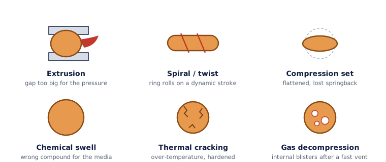
This page is the design-side view: the mechanism and the fix. If you have a failed part in hand and want to read the damage pattern to find the cause, use the Troubleshooting guide, which is built for exactly that.
The common failure modes
Extrusion and nibbling
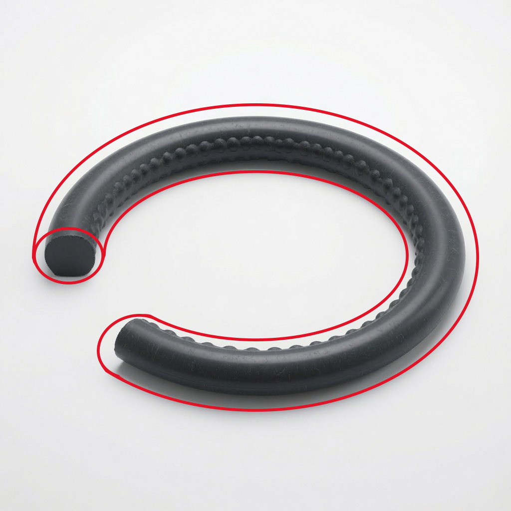
What happens: pressure pushes the ring into the clearance gap and nibbles a ragged edge off the low-pressure side. Design it out: tighten the clearance gap, step up to a harder 90-durometer compound, or add a back-up ring.
Compression set
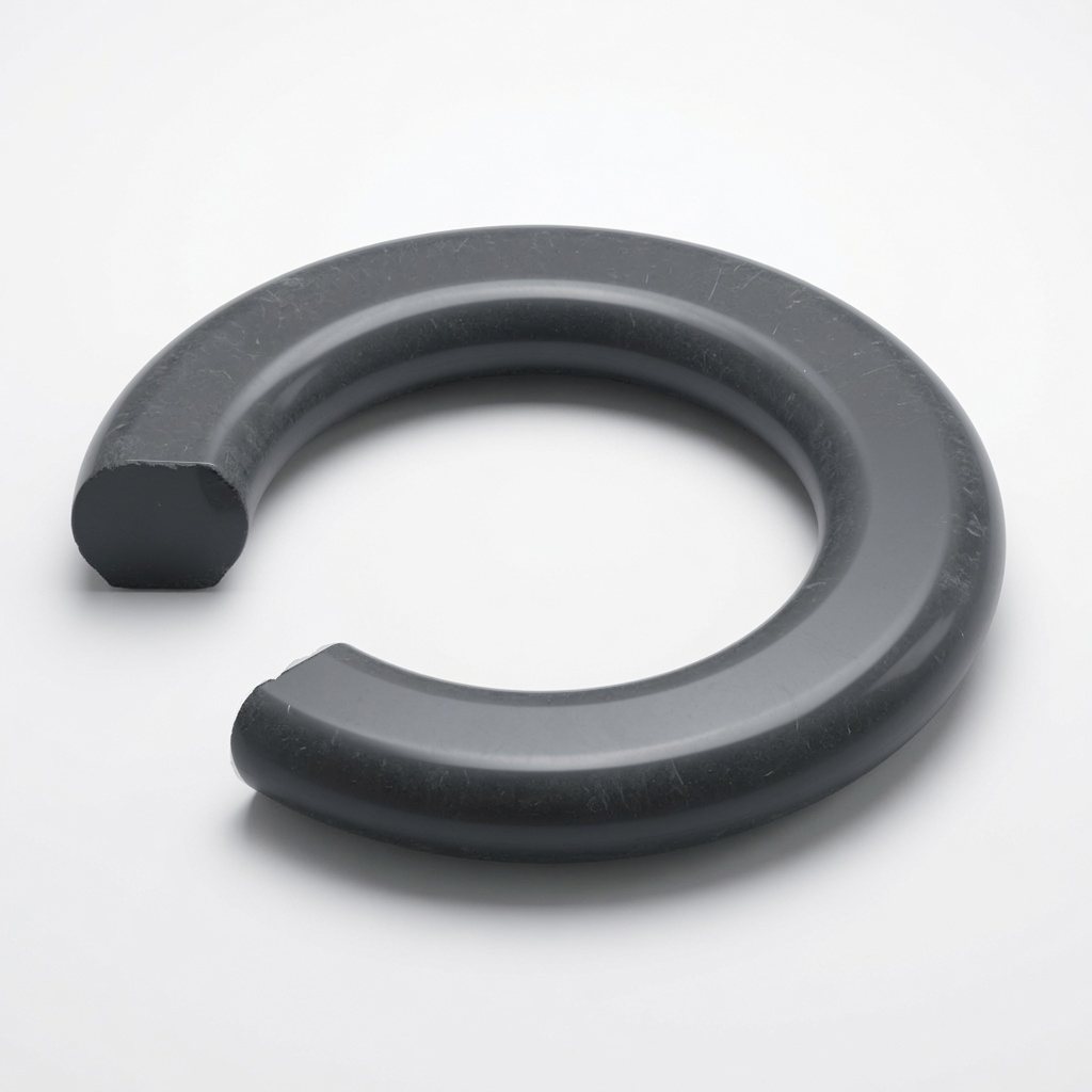
What happens: the ring takes a permanent flat and loses the springback it needs to seal. Caused by too much squeeze, too much heat, or a compound that can’t take the temperature. Design it out: hold squeeze in range, and pick a compound rated for your heat. FKM, FFKM, and silicone recover far better when hot. See Materials.
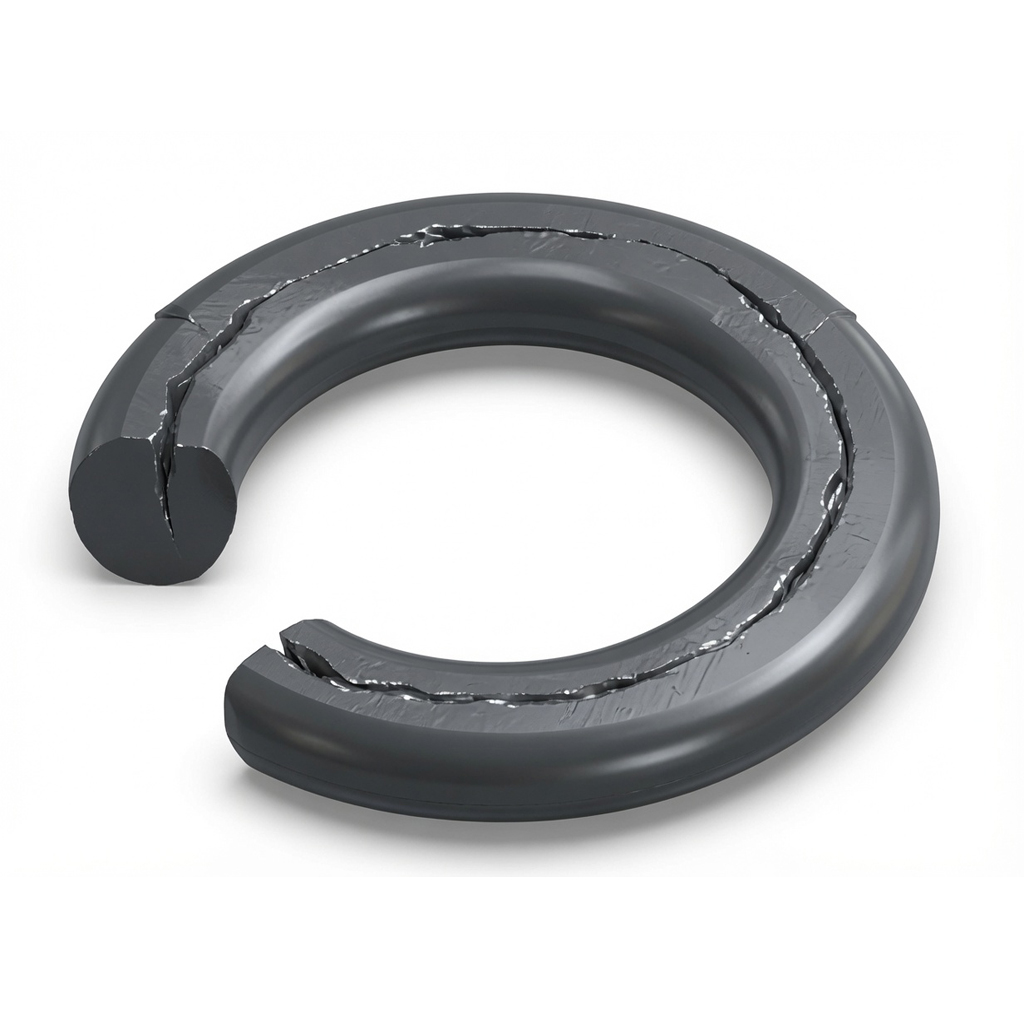
Spiral (twist) failure
What happens: on a dynamic stroke the ring twists and gets cut in an angled, spiral pattern around the cord. Common on long reciprocating rod and piston seals. Design it out: lubricate, cut groove eccentricity, use a thicker cross-section, or move to an X-ring, which resists twisting. See Seal Types & Profiles.
Chemical attack and swelling
What happens: the media is incompatible, so the ring swells, softens, or turns gummy and loses its shape. Design it out: check the compound against the fluid on the Chemical Compatibility chart before you order. This is the single most common avoidable failure.
Thermal degradation
What happens: over-temperature service hardens and cracks the ring, or on the cold end the rubber goes glassy and can’t follow movement, so it leaks with no visible damage. Design it out: stay inside the compound’s rated temperature band, both ends. The Materials table lists every range.
Explosive (rapid gas) decompression
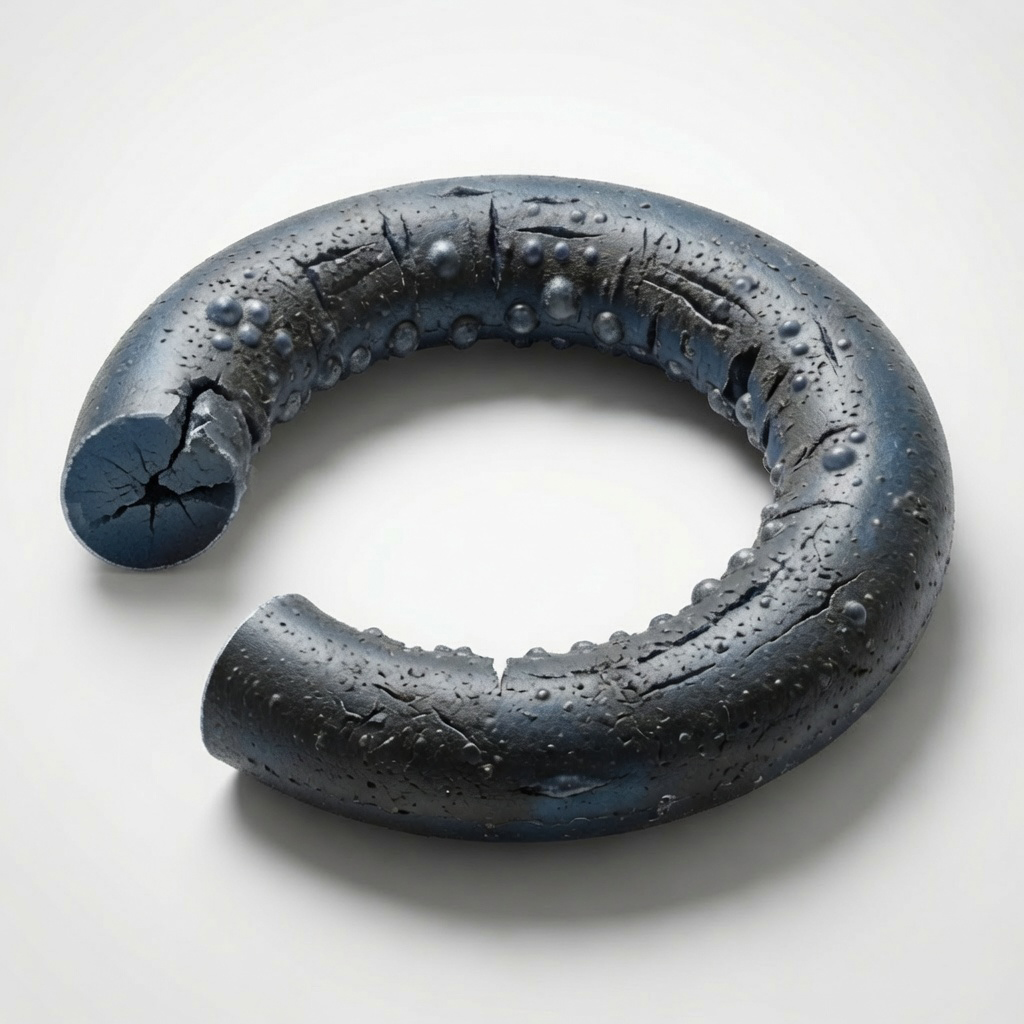
What happens: in high-pressure gas service, gas soaks into the rubber. When pressure drops fast, it expands and blisters or splits the ring from the inside. Design it out: decompress slowly, use a purpose-built decompression-resistant compound, and favor higher hardness and a smaller cross-section.
The pattern
Look back over that list and you’ll see the same handful of design levers, over and over: gap, squeeze, hardness, back-up ring, temperature rating, and media compatibility. Get those right on the Groove Design and Materials pages and the failures above mostly disappear.
For a deeper walk through prevention, the article Five Ways to Avoid Early Seal Failure is a good next read.
A stubborn or expensive failure is worth a second set of eyes. Send us the part and the application and we’ll help you run it down.
Failure mechanisms based in part on the Freudenberg FST 2025 Technical Manual, ch. 2 (Materials), §9 Damage Analysis. For compound temperature and media limits, see Materials and Chemical Compatibility.